Image segmentation
Intensity thresholding operators
threshold <threshold-value>
This operator performs a binarization of the input image by simple thresholding. Values that are strictly below the specified threshold-value in the input image are set to 0 in the output image. Input values that are equal or above the threshold are set to 1.
otsu-thresholding
This operator performs a binarization of the input image by thresholding using a threshold value automatically computed following Otsu’s method [Otsu, 1979]. The criterion for determining the best threshold is the separability between the two classes defined by the threshold. In Otsu’s method, separability is formally defined as the ratio between the between-class variance and the within-class variance. Intuitively, this corresponds to selecting a threshold that optimises simultaneously the contrast between the two classes and the homogeneity within each class.
isodata-thresholding
This operator performs a binarization of the input image by thresholding using a threshold value automatically computed following the method of Ridler and Calvard [Ridler and Calvard, 1978]. The method iterates separating the histogram into two classes using the current threshold value, computing the class averages, and setting the threshold for the next iteration as the middle point between the two averages. This is a 1D version of the \(k\)-means algorithm (with \(k=2\)), also known as Isodata algorithm. This method is also related to Otsu’s method [Xue and Zhang, 2012], and generally gives, at best, similar results.
unimodal-thresholding
This operator performs a binarization of the input image using a threshold value computed according to the “triangle” method [Zack et al., 1977], also known as unimodal thresholding [Rosin, 2001]. As the name indicates, this method was designed to compute intensity thresholds from histograms that do not exhibit strong bimodality, as is the case when the objects of interest cover a small portion only of the image. Our implementation assumes objects are bright over a dark background. In the reverse situation, the image should be inverted before computing the threshold. For example:
bip pipeline -e "invert auto | unimodal-thresholding"
hysteresis-thresholding <low-threshold> <high-threshold>
This operator performs hysteresis thresholding [Canny, 1986] on the input image(s).
Hysteresis can be described as a two-step process to compute the foreground pixels/voxels. First, all image sites with values above the high threshold are selected. Second, all image sites with values between the low threshold and the high threshold that are connected to sites above the high threshold (either directly or by the intermediate of other sites between these two values) are also retained in the output image. All other sites (below the low threshold or not connected to sites above the high threshold) are set to the background value.
Using hysteresis thresholding is more robust than using a single threshold (see operator thresholding), allowing to reach a better balance between sensitivity and selectivity in the determination of foreground pixels/voxels.
Watershed transform operators
watershed [-n 4,6|8,26]
This operator runs the classical watershed transform: starting from the regional minima of the input image, labels are progressively growing as if (virtually) flooding the image until they meet other labels.
The connectivity used for computing regional minima and for propagation in the watershed algorithm is set using the -n option. See Neighbourhood systems and connectivity for more information about the meaning and usage of this option.
To obtain relevant segmentation results with this operator, the input image should have high intensity values at the interfaces between objects. Applying a gradient operator is required if this is not the case, i.e., if the input image contains labelled objects rather than labelled object boundaries.
h-watershed [-n 4,6|8,26][-s] <h>
This operator runs the classical watershed transform after having filtered the input image. The filtering operation aims at reducing the over-segmentation problem that is frequently encountered when applying the classical watershed transform alone. The filtering consists in removing from the image the minima that are not significant, i.e., whose depth is below the specified h-value (Figure 5).
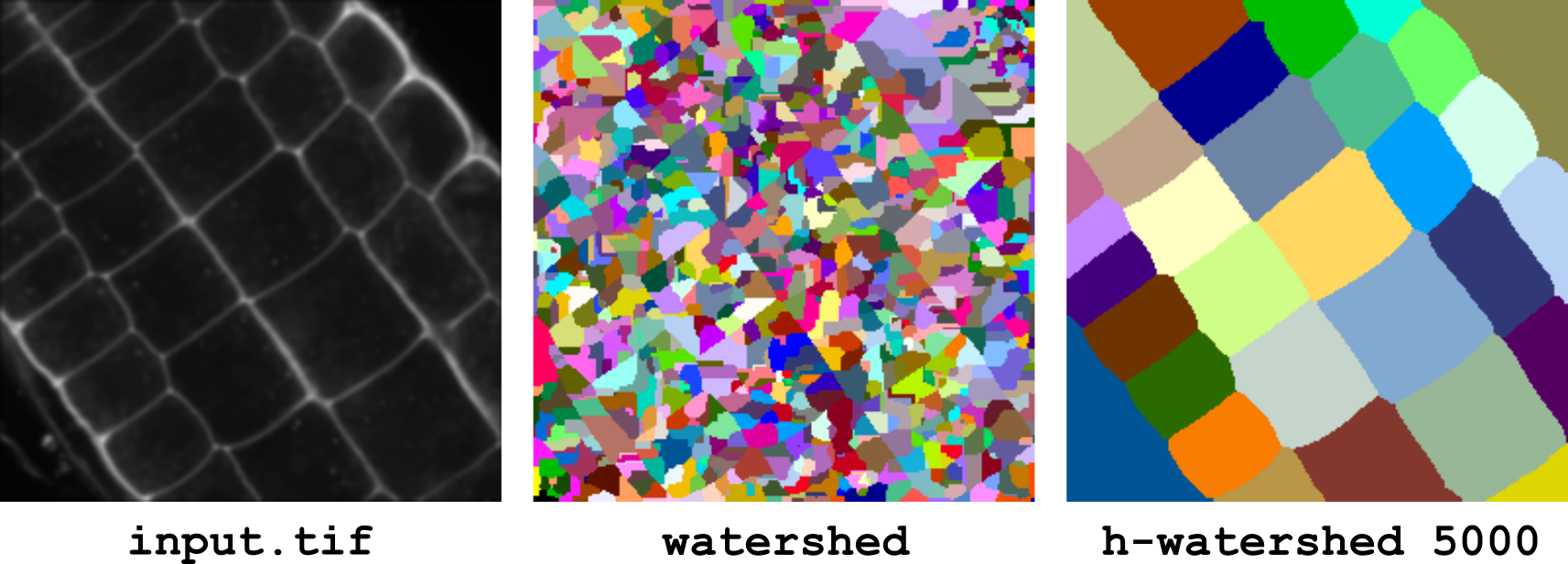
Figure 5 Watershed transforms. The input image (16 bits) has been processed either using the basic watershed transform (operator watershed) or with an additional preprocessing step to remove non-significant minima (operator h-watershed).
The connectivity used at the filtering step and for propagation in the watershed algorithm is set using the -n option. See Neighbourhood systems and connectivity for more information about the meaning and usage of this option.
To obtain relevant segmentation results with this operator, the input image should have high intensity values at the interfaces between objects. Applying a gradient operator is required if this is not the case, i.e., if the input image contains labelled objects rather than labelled object boundaries.
If the -s option is set, then the operator saves an image of the computed seeds. This allows users to perform corrections, typically by adding new seeds to fix under-segmentation issues (since over-segmentation can be corrected by merging labels using the replace operator, it does not necessarily require manipulating the seed image). Note modified seed images should be passed as marker image to the marker-watershed operator.
This operator is provided for convenience. It is equivalent to the following pipeline (using \(h=10\) in this example):
# converts image to 16-bit unsigned integer values
# (no effect if image is already 16-bit unsigned)
# and stores a copy for later retrieval in the pipeline
convert uint16
store $image

# removes non-significant minima
extended-minima 10
store $emin
recall $image
minima-imposition $emin

# applies watershed on the filtered image
watershed -n 8,26
marker-watershed [-n 4,6|8,26] <marker-image>
This operator runs the watershed transform using user-specified seed for initialization. The seeds, or markers, are used to pre-filter the input image and to remove regional minima not corresponding to any seed.
The seeds are taken from marker-image. Any connected set of non-zero values in this image is considered as a seed.
The connectivity used to define connected sets in the marker image and for propagation in the watershed algorithm is set using the -n option. See Neighbourhood systems and connectivity for more information about the meaning and usage of this option.
To obtain relevant segmentation results with this operator, the input image should have high intensity values at the interfaces between objects. Applying a gradient operator is required if this is not the case, i.e., if the input image contains labelled objects rather than labelled object boundaries.
Label operators
labelling [-n 4,6|8,26]
This operator performs a labelling of the connected components in an image. A connected component is a set of image positions within which any two positions can be connected by a path that never passes by background positions. The background is defined as the positions with value 0. These definitions of components and background imply in particular that this operator can be applied to binary images as well as to non-binary images. In the latter case, connected components are defined as sets of connected non-null values.
The connectivity used to define connected sets is set using the -n option. See Neighbourhood systems and connectivity for more information about the meaning and usage of this option.
condense-labels
This operator performs a renumbering of the labels in an image in order to obtain a consecutive sequence of label numbers. This is useful for example when some labels have been removed or merged. Applying this operator ensures in particular that the maximal value in a label image equals the number of labeled objects.
Note that a call to the labelling operator is generally not equivalent to a call to the condense-labels operator, as the first one would merge labels that are connected. In addition, the second one runs faster than the first one, since it operates on label values only and not on their spatial structure.
It is likely that users will use this operator almost exclusively on integer-type images. If needed (for example to avoid type conversion within a pipeline), it should be noted that it can as well be applied to real-type images, as long as the actual values are integers.
BIP makes no distinction between intensity and label images (this distinction is the responsibility of the user). Hence, although this operator is primarily intended for application on label images, it can also be applied to intensity images (though it is unclear which situation would benefit from such processing).
Evaluation of segmentation results
label-errors split|merge|split-merge <reference-image>
This operator selects the labels corresponding to under- and over-segmentation errors in the input image compared to the specified reference image (Figure 6). The errors are detected by first computing a forward mapping giving for each label of the reference image the label that intersects most in the input image. Similarly, a backward mapping is computed between the input image and the reference. An under-segmentation error occurs when two or more labels of the reference image are mapped to the same label in the input image. Reciprocally, an over-segmentation error occurs when two or more labels of the input image are mapped to the same label in the reference image.
The first argument of the operator is used to select the type of error that is computed. If set to split-merge, both under- and over-segmentation errors are computed. In this case, the output image contains two channels. The first channel gives the labels of the reference image that are under-segmented in the input image. The second channel gives the labels of the input image that are splitting some labels in the reference image.
If the first argument is set to merge or split, only the corresponding type of error is computed and the output image contains a single channel.
Restrictions: this operator cannot process multi-channel or multi-sample images.
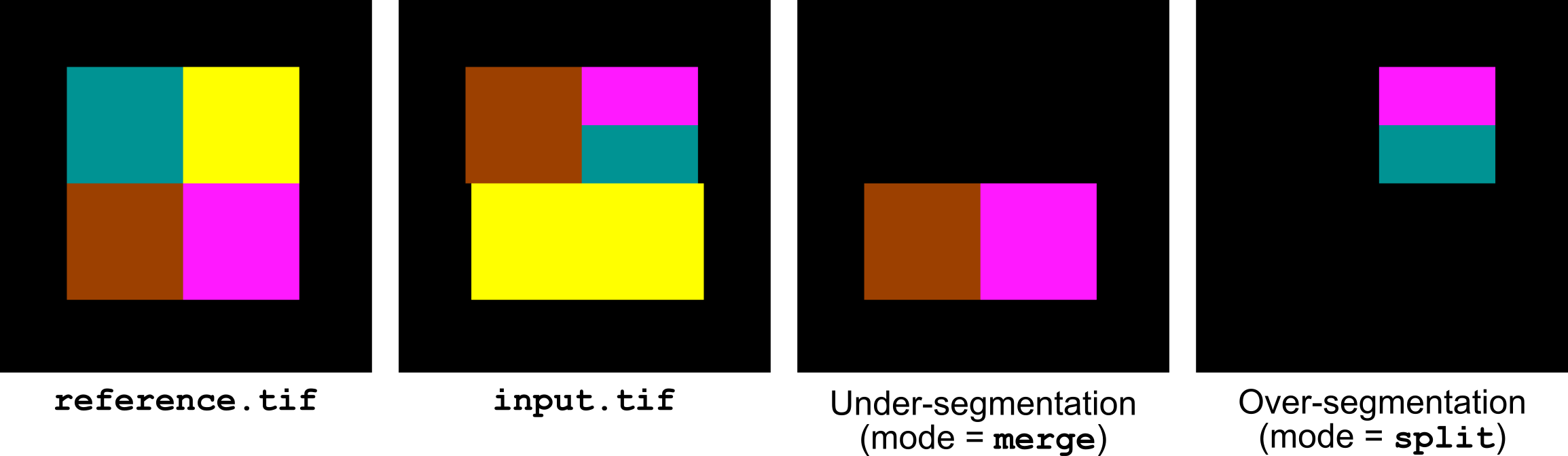
Figure 6 Highlighting under- and over-segmentation errors with label-errors.
Deep learning-based segmentation operators
cellpose [-e <env>][-m <model>][-d <diameter>][-c <channel>][-f <flow-threshold>][-p <cellprob-threshold>][-s <min-size>][--cpu][--edges][-v]
This operator segments cells or nuclei from an image using Cellpose, a generalist deep-learning segmentation tool [Pachitariu et al., 2025, Stringer et al., 2021]. It calls the Cellpose v4 command-line interface inside the conda environment specified with the -e option (default: cellpose) and returns the resulting instance mask. The specified conda environment must already exist and contain a working installation of Cellpose v4.
Users should take care of having Cellpose v4 installed on their system before using this operator.
The operator automatically runs in 3D mode whenever the input image has more than one plane along its third dimension.
Besides the -e option, the following options are available:
-mname of the pre-trained model to use (default:
cpsam, the Cellpose-SAM generalist model). Other built-in Cellpose models (e.g.,cyto3,nuclei) or a path to a custom model can be given instead.-dexpected object diameter in pixels (default:
30). This is the main parameter controlling segmentation scale; it should be set close to the typical diameter of the objects to segment.-cindex of the channel containing the objects to segment, when the input image has multiple channels. Left unset by default, in which case Cellpose’s automatic channel detection is used.
-fflow error threshold used to discard poorly reconstructed masks (default:
0.4); increasing this value keeps more masks but may include lower-quality ones.-pcell probability threshold used to determine which pixels belong to a cell (default:
0); decreasing this value yields larger, more numerous masks.-sminimum object size in pixels; objects smaller than this value are discarded (default:
15).--cpuruns the prediction on the CPU instead of the GPU.
--edgesdiscards objects touching the border of the image, which are often only partially imaged.
-venables Cellpose’s verbose logging, useful for diagnosing segmentation issues.
Example
# segment nuclei on the GPU, excluding nuclei touching borders
cellpose -m nuclei -d 25 --edges image.tif
plantseg [-v <version>] [-e <plantseg-environment>] [-c <config-file>] [-m <model>]…
This operator runs a Convolutional Neural Network called PlantSeg [Wolny et al., 2020] to enhance boundary signals in input images. It is typically applied on images of labelled cell membranes or walls before a watershed transform to segment cells within tissues. PlantSeg is a 3D-Unet architecture [Falk et al., 2019] that has been pre-trained on plant tissue images. The default model has been trained on 3D confocal image stacks of Arabidopsis thaliana ovules.
Users should take care of having PlantSeg/PanSeg installed on their system before using this operator.
The tool version is selected explicitly with the -v option (1 for PlantSeg, 2 for PanSeg, default: 1); it is never guessed from the conda environment. The corresponding conda environment is given with -e (default: plant-seg-1.8.1); it must contain a working installation of the selected tool.
In standard mode, the output of the operator is the predicted boundary probability map saved as a 16- or 32-bit image, depending on the underlying tool’s post-processing settings. When the -c option is used, the output depends on the configuration file (including any segmentation it enables).
Standard mode
In standard mode (the default, used whenever -c is absent), the operator builds a minimal configuration file internally and runs only the CNN prediction step; preprocessing, segmentation and postprocessing are all disabled. The following options control the prediction step and are common to both versions:
-mname of the pre-trained model to use (default:
generic_confocal_3D_unet). Refer to the PlantSeg/PanSeg model zoo for the list of available models.-ppatch size used to tile the volume for prediction, given as
X,Y,Z(default:64,64,64).--cpuruns the prediction on the CPU instead of the GPU.
--model-updateforces PlantSeg/PanSeg to re-download the specified model even if a local copy is already cached.
Two further options are specific to PlantSeg v1 (-v 1), and control how predictions on overlapping patches are stitched together:
-wnumber of parallel workers used for prediction (default:
8).--stride-ratiooverlap between adjacent patches, expressed as a fraction of the patch size (default:
0.75).
PanSeg v2 (-v 2) replaces the stride ratio by an explicit halo, and additionally allows batching of the patches sent to the network:
-hhalo added around each patch, given as
X,Y,Z(default:8,8,8); patches are predicted including this margin, which is then discarded when patches are merged, in order to reduce border artifacts.--single-batchprocesses patches one at a time rather than batching them (default: enabled); disable only if your environment supports batched inference and you want to trade memory for speed.
Options that do not apply to the selected version are simply ignored if left at their default value (e.g. -w has no effect when -v 2 is used).
Custom configuration mode (``-c``)
For full control over the pipeline – enabling preprocessing filters, running the bundled segmentation methods, or otherwise deviating from the minimal prediction-only pipeline – a configuration file produced by PlantSeg/PanSeg (or written by hand, following its schema) can be supplied with the -c option. In this mode the operator only patches the input image path and the output directory inside the file; every other field (filtering, segmentation, postprocessing parameters, etc.) is left untouched and entirely under the user’s control.
Because -c hands over full control of the prediction step to the configuration file, it cannot be combined with any of the prediction options listed above (-m, -p, --cpu, --model-update, and version-specific options such as -w, --stride-ratio, -h, --single-batch). Supplying -c together with any of these raises a usage error; edit the configuration file directly instead.
Examples
# PlantSeg v1.8, GPU prediction with a custom patch size
plantseg -v 1 -e plant-seg-1.8.1 -m generic_confocal_3D_unet \
  -p 128,128,32 image.tif

# PanSeg v2.0, CPU prediction with default model and halo
plantseg -v 2 -e panseg-2.0 --cpu image.tif

# Full control via a hand-edited PanSeg workflow file
plantseg -v 2 -e panseg-2.0 -c my_workflow.yaml image.tif