Image transforms
Image size
enlarge <margins>
This operator increases image size by adding margins.
The margins are specified in pixels (2D) or voxels (3D). If a single value is specified, it is interpreted as the margin in all XY(Z) directions. It two values are specified, they are interpreted as the X and Y margins, respectively. The Z margin is then set to 0, in case 3D images are processed. If three values are specified, they are interpreted as the XYZ margins.
Example 1. Increasing image size by 10 pixels/voxels on all sides:
bip enlarge 10 image.tif
Example 2. Adding 10 slices at the top and at the bottom of a 3D image:
bip enlarge 0,0,10 image3D.tif
isoscale nearest|linear
This operator resizes the input image using interpolation in order to obtain an output image with an isotropic spatial calibration (i.e., as if its spatial sampling was isotropic). For example, an input image with voxel size of 0.5,0.5,1.0 micron would have its number of slices doubled by this operator, thus yielding a voxel size of 0.5,0.5,0.5 micron.
The operator automatically determines which direction(s) should be resampled. The direction(s) with the smallest spatial sampling is preserved, and the other direction(s) are upsampled. Note that because of the discrete nature of digital images, it is not always possible to obtain an exactly isotropic element size.
The parameter of the operator specifies the interpolation mode. As a rule of thumb, it is recommended to use the linear mode in all cases except when processing binary or label images, for which averaging values is meaningless. For these images, the parameter should be set to nearest (no interpolation).
resample nearest|linear <dx,dy[,dz]>
This operator resizes the input image using interpolation so that the resulting image has the specified <dx,dy[,dz]> spatial calibration. When processing 2D images only, dz can be omitted. Be warned, however, that dz defaults to 1.0, so that the voxel depth of 3D images can be modified even if this argument is not specified.
Note that because of the discrete nature of digital images, it is not always possible to obtain an output image with exactly the same spatial calibration as the one specified by the user.
The first parameter of the operator specifies the interpolation mode. As a rule of thumb, it is recommended to use the linear mode in all cases except when processing binary or label images, for which averaging values is meaningless. For these images, the parameter should be set to nearest (no interpolation).
reslice x|rx|y|ry
This operator reslices the input image along the specified axis and direction. The image is assumed to be 3D (the image is left unchanged by the operator otherwise). The reslicing is controlled by the parameter passed to the operator:
xreslices the image from left to right;
rxreslices the image from right to left;
yreslices the image from top to bottom;
ryreslices the image from bottom to top.
scale nearest|linear <factor>
This operator resizes the input image in all directions according to the specified scale factor. The spatial calibration of the image is updated accordingly.
The first parameter of the operator specifies the interpolation mode. As a rule of thumb, it is recommended to use the linear mode in all cases except when processing binary or label images, for which averaging values is meaningless. For these images, the parameter should be set to nearest (no interpolation).
shrink <margins>
This operator decreases image size by removing margins.
The margins are specified in pixels (2D) or voxels (3D). If a single value is specified, it is interpreted as the margin in all XY(Z) directions. It two values are specified, they are interpreted as the X and Y margins, respectively. The Z margin is then set to 0, in case 3D images are processed. If three values are specified, they are interpreted as the XYZ margins.
Example 1. Decreasing image size by 10 pixels/voxels on all sides:
bip shrink 10 image.tif
Example 2. Removing 10 slices at the top and at the bottom of a 3D image:
bip shrink 0,0,10 image3D.tif
Image structure
projection avg|max|min
This operator performs the 2D projection of the input image along the Z direction. The input image is assumed to be 3D. In the 2D case, the output is identical to the input.
The parameter of the operator specifies the projection mode. If set to avg, values are averaged along the Z direction for each XY position. If set to max, the maximum value along the Z direction is retained for each XY position (this also known as MIP, Maximum Intensity Projection). And yes, min does what you expect it does.
merge-channels
This operator takes as input a list of images and merges them as different channels into a multi-channel image as output. The input images must have the same XYZ size, the same numerical type, the same number of samples per pixel, and the same number of timepoints.
Note the input images can be themselves multichannel images. The total number of channels in the output image is thus the sum of the number of channels in the input images. This features allows for example to add a new channel to a pre-existing multi-channel image.
merge-slices <dz>
This operator takes as input a list of 2D image files and concatenates them into a 3D image stack as output. The input 2D images must have the same XY size, the same numerical type, the same number of samples per pixel, and the same numbers of channels and of timepoints.
The parameter dz is the Z-spacing between the slices in the generated stack (a.k.a. voxel depth). It should be expressed in the same length unit as the XY calibration of the input images.
For example, one would call the following to merge slices with a 0.123 Z-spacing:
bip merge-slices 0.123 slice1.tif ... sliceN.tif
merge-timepoints
This operator merges input images along their temporal dimension. Any number of images, containing each an arbitrary number of timepoints, can be merged. The only condition that the images must satisfy is that their other dimensions (XYZC), their value types, and their spatial calibrations are identical.
The output filename is generated from the basename of the last specified image.
split-channels
This operator splits the different channels contained in the input image into as many separate files. Individual channel files are numbered starting from 0. Filenames are padded with ’0’s to ensure a constant filename size.
No output file is generated if the input image contains a single channel.
split-slices
This operator splits the input 3D image into as many separate files corresponding to its 2D slices. Individual slice files are numbered starting from 0. Filenames are padded with ’0’s to ensure a constant filename size.
The generated 2D images contain the same number of channels and timepoints as the input image.
No output file is generated if the input image is not a 3D image.
split-timepoints
This operator splits the different timepoints contained in the input image into as many separate files. Individual timepoint files are numbered starting from 0. Filenames are padded with ’0’s to ensure a constant filename size.
No output file is generated if the input image contains a single timepoint.
Other transforms
auto-crop [-m <margin>]
This operator automatically crops the input images around their non-background contents. The background value is controlled by the -B global option (default is 0). A margin can be added around the bounding box using the -m option (expressed in pixels/voxels).
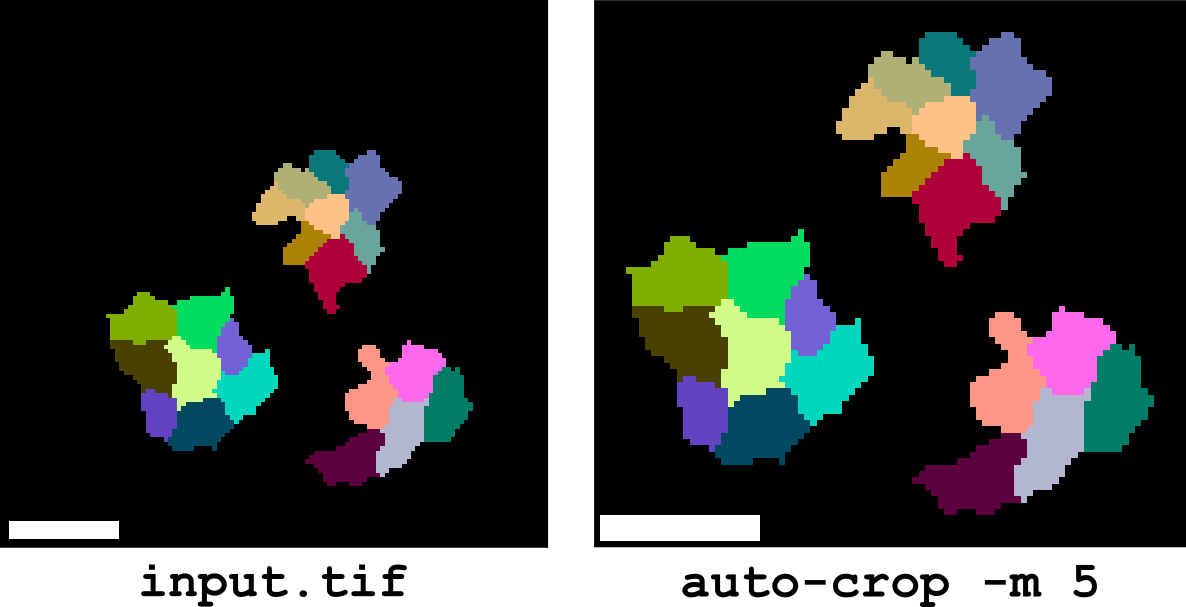
For multi-channel and multi-timepoint images, the crop is performed using the union of the boundings boxes of individual images.
crop <i0,j0[,k0] <i1,j1[,k1]>
This operator crops the input image to a specified bounding box. The bounding box is defined by its starting corner i0,j0[,k0] and its ending corner i1,j1[,k1]> in the image’s coordinate space (IJK).
crop-from [-m <crop-margin>] <label-image-path>
This operator computes the bounding boxes of the labelled objects found in the label image specified by label-image-path and uses these bounding boxes to crop the input image(s) into as many sub-images (Figure 2). The output sub-images are stored in separate files, with filenames obtained by appending label numbers to the basename of the input image file.
The -m option can be used to add a margin around the crop region. The margin width is expressed in pixels/voxels.
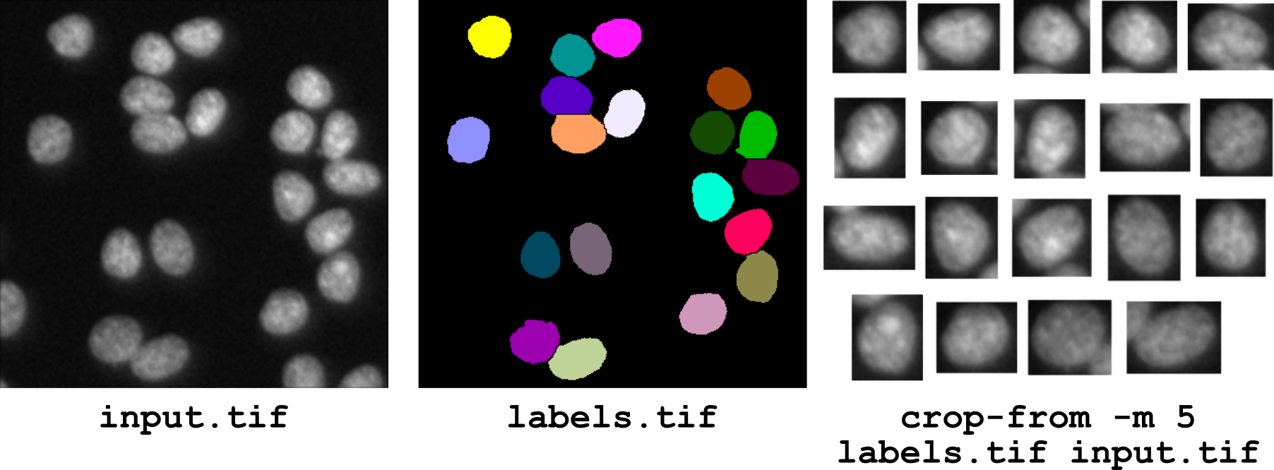
Figure 2 Cropping an image from a label image: operator crop-from.
The crop-from operator can also be used to split the segmentation masks of the different objects present in a segmented image. In this case, the label image is specified twice on the command line, first as the image to compute the crop boxes, and second as the image to be cropped:
bip crop-from -m 1 labels.tif labels.tif
fft
This operator computes the fast Fourier Transform of the input image. Only images with 1 sample per image position can be processed (multi-channel images are supported). The output images have 2 samples, the first one storing the real part and the second one storing the imaginary part of the complex numbers of the Fourier Transform. Note that the origin (zero-frequency component) is not centered in the output image (no swap of quadrants).
norm
This operator computes the norm of the input image. This operator is meaningful for vector images only, i.e., images in which several values (samples in the TIFF nomenclature) are associated to each image position (such as gradient or FFT images). The computed norm is the Euclidean (L2) norm: